Introduction
This documentation consists of the following steps that are involved in the bring up of the SAFMC Drone, or otherwise known as the NUSwarm drone:
- Mechanical Assembly and System Integration
- Flight Controller setup and configuration
- On-Board Computer setup and configuration
1. Mechanical Assembly and System Integration#
Components Required#
These are the components required to build a SAFMC Drone:
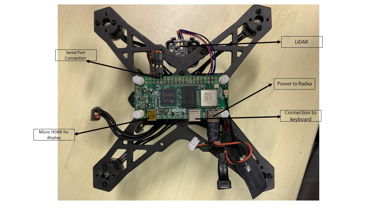
- On-Board Computer(OBC): Radxa Zero - Radxa Zero is an ultra thin SBC in small form factor with powerful performance based on Amlogic S905Y2. It can run Android and selected Linux distributions.
- Ideally the specs are 4GB Ram and 32gb emmc
- Product Link
- Other Links
note
Make sure to connect the Radxa Zero antenna (if board has external antenna support), before plugging in the power supply!
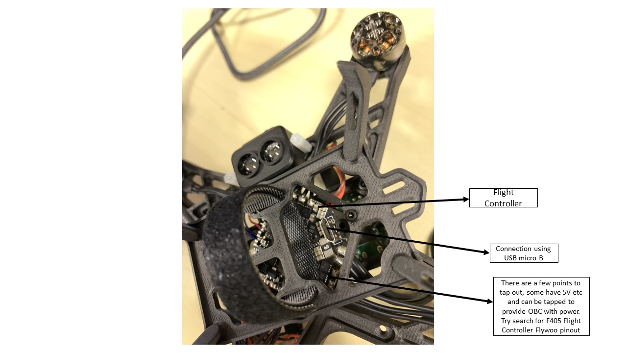
- Flight controller (FC): Flywoo Goku GN405S AIO - This is the low level controller that runs the PX4 flight control stack.
- MCU: STM32F405 BGA
- IMU: ICM42688/MPU6000
- Barometer: SPL06
- Onboard LED:WS2812*4
- 6 hardware UARTS (UART1,2,3,4,5,6)
- Supports serial receivers (SBUS, iBus, Spektrum, Crossfire) only.
- Onbord 8Mbytes for Blackbox logging
- 5V Power Out: 2.0A max
- 3.3V Power Out: 0.5A max
- Integrated ESC
- Support BLHELI_S
- Support PWM, Oneshot125, Oneshot42, Multishot, Dshot150, Dshot300, Dshot600
- Input Voltage: 2-6S Lipo
- Continuous Current: 20A(ICM42688)/40A(MPU6000)
- Firmware: BLHELI_S
- Product Link
Motors: Flywoo NIN 1404 V2 Ultralight FPV Motor (4850kV)
Propellers: HQProp T3x3x3
Lidar: TF-Luna V1.2
Serial Receiver
- FM800 (FASST RX)
- OR FrSky R-XSR/RXSR Ultra mini S.BUS Smart Port Redundancy Receiver for FPV Drone
Power supply
- Should be a 3S battery with XT-30 connector
Frame
- To obtain from relevant contributors/maintainers.
Wiring Guide#
- Refer the below image of the Flywoo Goku GN405S AIO flight controller board's wiring diagram for wiring and integration
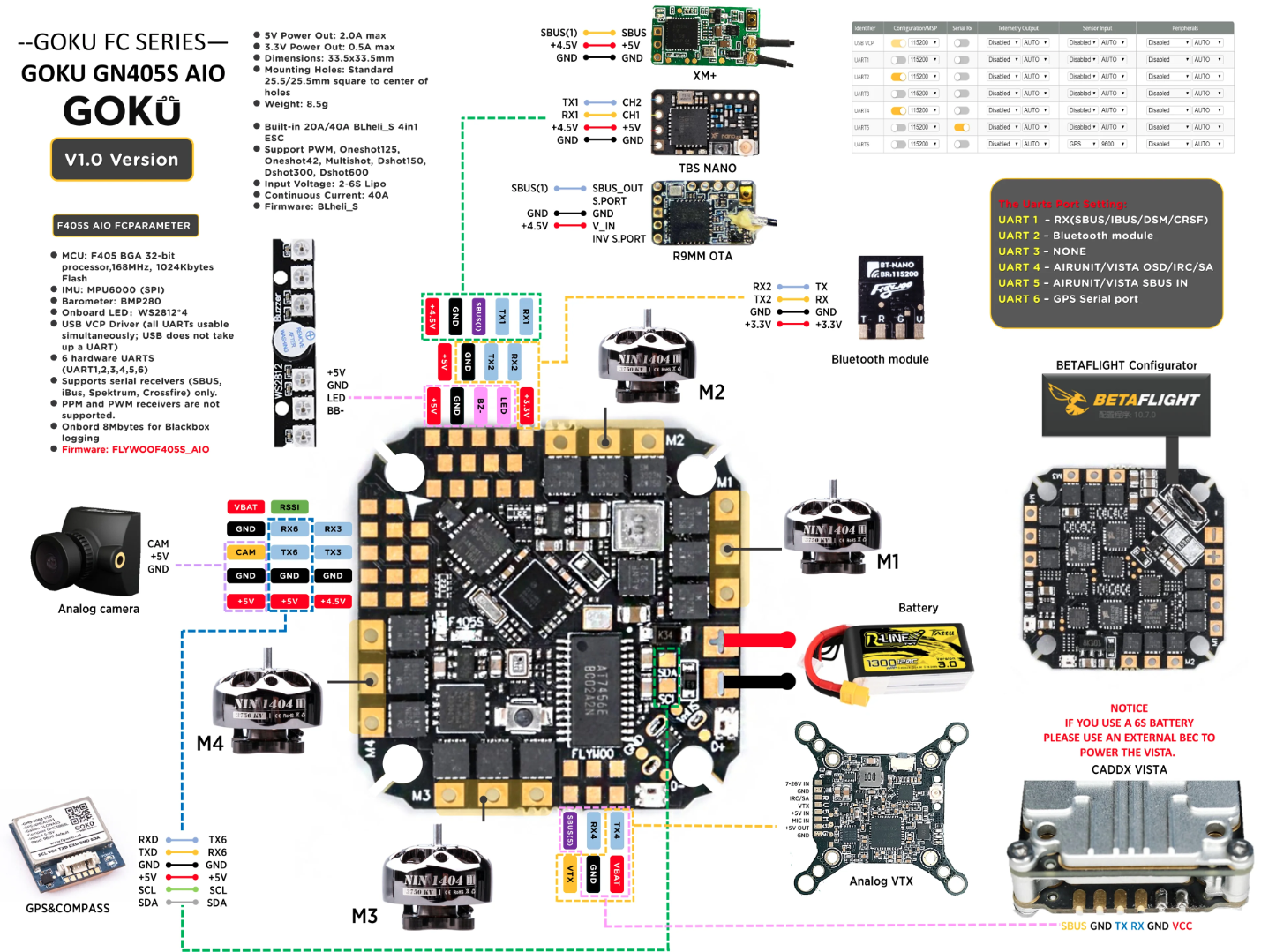
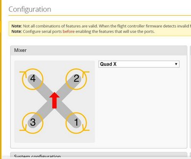
- Motors are wired in betaflight motor ordering. Refer the image below for reference.
Wiring for serial communication between FC and OBC should be established as given below in the table
|Flight Controller|On-Board Computer| |_|_| | TX4 | UART_AO_B_RX | | RX4 | UART_AO_B_TX | | GND | GND |
OBC is powered from flight controller's +5V power out through USB-C port on OBC
RC Rx is connected to the SBUS port of the FC
Make sure you know what serial ports are available on the flight controller. Refer
boards/flywoo/f405s_aio/nuttx-config/include/board.hin the board firmware code for Flywoo GN405S AIO board- UART 1 <-> /dev/ttyS0
- UART 1 is used for communicating via USB
- UART 2 <-> TEL1/101 (/dev/ttyS1)
- UART 4 <-> TEL2/102 (/dev/ttyS2)
- UART 6 <-> UART6 (/dev/ttyS3)
- UART 1 <-> /dev/ttyS0
Recommendation: It is recommended to use the capacitor (accompanied with the FC), as they help to reduce voltage spikes and electrical noise in the power system.
- Connecting RF receiver to the Flight Controller:
- Refer to wiring diagram above and you can see some pinouts stating 4.5V, GND and SBUS. Solder the wires to a connector such that you can connect it to the RF receiver.
- Then refer to the figure below and you can see how the wires should be connected to the connector. Once done, you can plug the RF receiver to the connector accordingly.
RC Tx & Rx Binding Procedure:
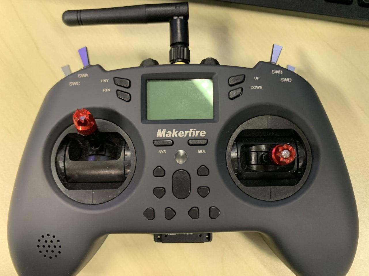
- With that, you can set up the RC Transmitter (RC Tx)/Radio (in this case we are using the remote control as seen below) to pair with the RC Receiver (RC Rx).
- Put the RC Tx into binding mode. Use to following settings on RC Tx (If using Frsky R-XSR RC Rx)
#Under SETUP Page Internal RF Mode MULTI Type FrskyX2 Subtype D16- Connect battery/power supply to the receiver while holding the F/S button on the RC Rx, the RED LED flashing indicates binding successfully
- Reboot the RC Rx and go back to normal mode on RC Tx. GREEN LED constant on RC Rx indicates linking is normal
- Refer to the RC Rx manual for more informations
Additional Information#
Adding ESP32 Radio#
ESP32 is a radio that is faster than communicating via the TCP/IP protocol. It can be integrated with the flight controller board. One ESP32 radio will be attached to the Drone via serial port while the other will be attached to the ground laptop (USB port). In general, some code will be uploaded into the ESP32 board which allows it to transmit and receives messages continuously from its serial connection.
To start writing the code to be uploaded into the radio, you need have an arduino IDE and set up your IDE to work with ESP32 board (because it requires prerequisite packages like esp_now.h etc). Look here
https://randomnerdtutorials.com/installing-the-esp32-board-in-arduino-ide-windows-instructions/.Afterwhich, you can start writing the code to be uploaded. Some examples are as follows:
https://randomnerdtutorials.com/esp-now-two-way-communication-esp32/For actual flight, you need to make sure the baud rate at which each radio is receiving and transmitting is the same (recommended 57600). For the ESP32 boards, this has to be configured in the code that you will upload to the board. For the drones, you have to configure it in the QGroundControl.Set baud rate telem2 to 57600 (or which ever baud rate to be consistent).
2. Flight Controller setup and configuration#
Updating ESC Firmware#
- Make sure to update the ESC firmware before flashing the PX4 Bootloader (i.e.) with native Betaflight bootloader
- Connect the battery to the flight controller and connect the flight controller to the computer via USB
- Use BLHeli Configurator to check and update the ESC firmware
- Reboot the flight controller
- Use Betaflight Configurator to check the motor directions. The motor directions (prop-in configuration) and numbering should be the same as indicated in the below image.
- If the motor direction are not same as indicated in the image, note the motor number and use BLHeli Configurator to change the motor direction.
PX4 Bootloader Flashing#
note
- Since Flywoo GN405S doesn't have native PX4 support, PX4 bootloader has to be built and flashed.
- Flywoo GN405S has similar architecture to the OmnibusF4SD board. Thus PX4 Bootloader for OmnibusF4SD can be utilized.
- Clone the PX4 Bootloader repository and build the bootloader as below.
#Clone the PX4 Bootloader repository from githubgit clone https://github.com/PX4/PX4-Bootloader.gitcd ./PX4-Bootloader#Build the PX4 Bootloader for the OmnibusF4SD flight controller boardmake omnibusf4sd_bl
INFO:
- If any python based error occurs, use
sudo apt install python-is-python2.- If any PX4 build error occurs, setup the PX4 developer environment using
Step 1of Building and flashing PX4 firmware, and repeat the above procedure.
- The build file should be available in
path_to/PX4-Bootloader/build/omnibusf4sd_bl - Install the PX4 Bootloader using Betaflight configurator
- Connect the flight controller to the computer using USB and start the Betaflight configurator
- Click
Update Firmwareon the top right corner and clickLoad Firmware [Local]on the bottom right corner - Select the bootloader file (preferred
hexfile) from the system and flash the board
- Reboot the system. Reconnect the flight controller to the computer and use the command on terminal
dmesg -wto verify the connection [On Linux Computers]
Building and flashing PX4 firmware#
- Set up the PX4 developer environment
# Clone the custom version of PX4 git clone https://github.com/JohnTGZ/PX4-Autopilot.git --recursive -b f405_aio_v1.13.0# Run the ubuntu.sh with no arguments (in a bash shell) to install all dependencies# Acknowledge any prompts as the script progressbash ./PX4-Autopilot/Tools/setup/ubuntu.sh
- Build the PX4 for you specific board
cd ./PX4-Autopilotmake <board_name>
- The following list shows the build commands for the various Flywoo F405S flight controller models
- Flywoo GOKU GN405S 20A AIO (ICM42688) :
flywoo_f405s_aio_icm42688p - Flywoo GOKU GN405S 40A AIO (MPU600) :
flywoo_f405s_aio_mpu6000
- Flywoo GOKU GN405S 20A AIO (ICM42688) :
#Examplecd ./PX4-Autopilotmake flywoo_f405s_aio_mpu6000
INFO: Use
make list_config_targetscommand on terminal to find the list of available board configurations
- Flash the build firmware
- Connect the flight controller to the computer and use the command below from PX4-Autopilot directory to flash the firmware
make <board_name> upload
- Reboot the flight controller
System setup and configuration using QGroundControl#
- Connect the flight controller to the computer
- Open QGrooundControl software, the drone should be detected automatically and connection should be established
- Navigate to
App Menu(QGC Logo) --> Vehicle Setup - Follow the list of setup options available under
Vehicle Setupto configure your drone specific to your application - Example: Under
Airframesetup option, selectQuadrotor X_Generic Quadrotor, if you're planning to use Quadrotor X configuration. - Perform sensor calibration under
Sensorssetup option - If RC Tx & Rx Binding process was successful in above steps, perform the radio calibration under
Radiosetup option - Under
Flight Modessetup option, setup the assign the required flight modes to you radio switch.IMPORTANT: It is mandatory to setup up
Emergency Kill switch channel - Setup the battery parameters under
Powersetup option - Before using
Motorssetup option to check the motor directions. Make sure the parameter 'MOT_ORDERING' is set to1to use Betaflight motor ordering, as the Flywoo boards are native Betaflight flight controllersIMPORTANT: You are required to power up the drone using battery to check the motor directions. Make sure propellers are not attached!
- Use
Safetysetup option to configure failsafe and safety features - You can use
Parametertab to configure any additional parameter specific to your project.INFO: Refer PX4 Parameter Reference Some parameters may be deprecated based on firmware versions, try changing
Versionon documentation page and look for parameters for more details - Perform a basic flight test to observe the vibrations and oscillation, and perform PID if required.
note
- If you are using pre-defined parameters loaded from saved file, update the parameter twice (i.e,.) upload the first time and reboot, upload the parameter the second time and reboot.
- After parameters are all set, make sure to calibrate Gyro, Accel and Level under
Sensors. Since you update the parameter from a pre-saved file, the calibration offset will be specific to that board, so it is mandatory to repeat the sensor calibration after parameter are loaded and saved.
Additional Information#
Parameter Configuration#
INFO: Given below are some parameters list for reference
################# Communication/Serial ports################  baud rates:    SER_TEL1_BAUD: 230400     SER_TEL2_BAUD: 230400 # Can be used for companion computer     SER_UART6_BAUD: 9600 # Can be used for lidar   GPS:    GPS_1_CONFIG: Set to 0 # Disabled unless using  Lidar:    SENS_TFMINI_CFG: Set to UART6   Mavlink:    Connection to companion computer:      MAV_0_CONFIG: TEL2/102       MAV_0_MODE: 2 (ONBOARD)      MAV_0_RATE: 0 (Half maximum)      MAV_0_FORWARD: 0 (DISABLED)    Connection to Lidar:      MAV_1_CONFIG: UART6       MAV_1_MODE: Normal      MAV_1_RATE: 1200 Byte/s      MAV_1_FORWARD: True
################# Lidar/Range finder (If using)################  EKF2_RNG_AID: Set to 0 to disallow use of range sensor.  Position offset should be 0.0:    EKF2_RNG_POS_X, EKF2_RNG_POS_Y, EKF2_RNG_POS_Z   Other values:    EKF2_MIN_RNG: In units of meters. Set to 0.04m (or whatever your sensor reading tells you when your drone is on the ground). This is the expected rangefinder value when on the ground.
################# Vicon (If using)################  EKF2_AID_MASK:     All other bits to false    Bit 3: Set to true to enable vision position fusion    Bit 4: Set to true to enable vision yaw fusion  EKF2_EV_NOISE_MD: Set to true. This is so that we can use noise values from PX4 parameters directly.
################# EKF2 ################  SYS_MC_EST_GROUP: Set to EKF2  EKF2_HGT_MODE: Set to 2 (If lidar is used)  EKF2_MAG_CHECK: Set to 0  EKF2_MAG_TYPE: If no magnetometer, set to NONE. Else AUTOMATIC
################# Position control ################  MPC_ALT_HOLD: Set to 2 (requires distance sensor)  MPC_THR_HOVER: Set to % required to achieve hover  MPC_LAND_SPEED: Rate of descent, can leave as default
################# Others ################  Checks    COM_ARM_WO_GPS: Allow arming without GPS Values    COM_RC_IN_MODE: Set to enable RC checks (if testing with a single drone)    CBRK_SUPPLY_CHK: If disabling voltage check, set to 894281  Auto disarm timeouts    COM_DISARM_PRFLT: Timeout for auto disarm if vehicle is too slow to takeoff.  Arming/Disarming    MAN_ARM_GESTURE: Enable arming/disarming via stick gestures  Motor ordering    MOT_ORDERING: Set to 1 for betaflight. This is because the default motor ordering on the Flywoo GN405 is for betaflight.  Sensor    SENS_BOARD_ROT: Set to Yaw 270 degrees
################# Battery################  Set the number of cells. Should be 3S.  Set the voltage divider value (There is a bug that it cannot be changed if the initial value is -1.0, so set it to a random positive value first. Then calculate it with the real value)
PX4 MAVLink Console troubleshooting#
NOTE: Given below are some mavlink console troubleshooting commands to use under
App Menu(QGC Logo) --> Analyze Tools --> MAVLink Console
# Communicationuorb statusmavlink status streams
# List processestop
# List all modulesls /bin/
# Listen to topicslistener TOPIC
# Modules## Get Distance sensor statustfmini status## Get sensors statussensors status
3. On-Board Computer setup and configuration#
Following are the steps to be followed to setup and configure the Radxa Zero OBC,
- Remove auto-boot (i.e. Create an access point to the FCU)
- Flashing of Ubuntu server image
- Enable headless mode
- Connecting to wifi network
- Synchronization of time in isolated network (no internet connection)
- Interfacing with PX4
- Additional information. Important for debugging.
1. Remove autoboot (i.e. Create an access point to the FCU)#
note
This is only required if you are using GPIO Pin 8,10 and 11
There's a need to create an access point by removing auto-boot from the radxa bootloader. When we power on the OBC, what the bootloader will usually do is that it will keep do a countdown and check for any disruption. So if we have the serial port of OBC connected to the flight controller, then there will be some input signal going to the serial port and hence it keeps disrupting the bootloading process. Therefore the OBC cannot boot up.
So the following instructions configures the bootloader to go into fastboot mode, which means don't do a count down and just immediately boot up. Which means you have to amend the config file to the bootloader.This bootloader is also stored in the eMMC. So how should we amend this config file? We have to clone the bootloader from the radxa github page, rebuild the binaries, ie u-boot.bin and then replace the u-boot.bin file in the eMMC (which is the dd step in the instruction).
Install dependencies:
sudo apt-get install -y wget bc nano mc build-essential autoconf libtool cmake pkg-config git python-dev swig libpcre3-dev libnode-dev gawk wget diffstat bison flex device-tree-compiler libncurses5-dev gcc-aarch64-linux-gnu g++-aarch64-linux-gnu binfmt-support binfmt-support qemu-user-static gcc-aarch64-linux-gnu gcc-arm-linux-gnueabihf fastbootGit clone 2 packages
git clone --branch radxa-zero-v2021.07 https://github.com/radxa/u-boot.gitgit clone https://github.com/radxa/fip.gitEdit the radxa zero config in the u-boot repo
nano u-boot/configs/radxa-zero_defconfig#Add **CONFIG_BOOTDELAY=-2** before **#CONFIG_DISPLAY_CPUINFO is not set**Compile from
u-bootcd u-bootexport ARCH=armexport CROSS_COMPILE=aarch64-linux-gnu-make radxa-zero_defconfigmakeCompile from
fip/radxa-zerocp u-boot.bin ../fip/radxa-zero/bl33.bincd ../fip/radxa-zeromakeCopy u-boot.bin over
Sideload (Safer option)
Hold down boot button on radxa and connect to PC, then run:
sudo boot-g12.py /path/to/fip/radxa-zero/u-boot.bin
(ONLY AS LAST RESORT) Use dd to write over the eMMC
Hold down boot button on radxa and connect to PC. Run the following command to expose the Radxa as a mountable disk
sudo boot-g12.py rz-udisk-loader.binUse
dmesg/lsblkto figure out whatsdXis RadxaIn fip/radxa-zero, run the following command to copy the files over
sudo dd if=u-boot.bin of=/dev/sdX bs=512 seek=1
Reboot the device
2. Flashing of Ubuntu Server image#
Here, we focus on flashing the Ubuntu OS into the OBC via eMMC. eMMC is like a non-volatile storage device. There is also another way of flashing using microSD card. An introduction is listed here: https://wiki.radxa.com/Zero/getting_started.
Install the following tools on your main computer:
sudo apt updatesudo apt install python3-pipsudo pip3 install pyamlbootErase eMMC of Radxa
- Press down boot button on Radxa before powering it on and connecting it to the PC. NOTE: Button must be pressed down WHILE physically connecting it via USB to the computer.
- Download
radxa-zero-erase-emmc.binANDrz-udisk-loader.bin - Run
sudo boot-g12.py radxa-zero-erase-emmc.bin- This will automatically erase eMMC, then present eMMC as a USB storage device.
- Reference
Install Balena Etcher
Flash Ubuntu OS onto Radxa
- Download images from here, the file name should be something like
radxa-zero-ubuntu-focal-server-arm64-XXX-mbr.img - Decompress images using
xz -v --decompress IMAGE_COMPRESSED - Use BalenaEtcher to mount the image. After step 2 (erasing the eMMC), the radxa eMMC should appear as a flashable device
- Download images from here, the file name should be something like
Once the OBC is flashed, then when you power on the OBC, it will now run the Ubuntu OS. To start up Radxa standalone, you need to:
- Plug in the power port from an external power supply
- Connect the keyboard
- Connect micro HDMI from the OBC to a monitor
- Once started up, username and password are 'rock'
3. Enable headless mode#
Disable debug port on OBC. This is so that the Flight controller unit can communicate with the radxa. Edit /boot/uEnv.txt and remove line with console=ttyAML0,115200, which removes this port as a debugging console.
4. Connecting to wifi network#
# Proceed on activating WIFI using https://wiki.radxa.com/Zero/Ubuntu# Root username and pasword is rock/rocksudo susudo nmcli r wifi onsudo nmcli dev wifisudo nmcli dev wifi connect "wifi_name" password "wifi_password"
Optionally, you can set network priorities to prioritize which network to connect to:
# List priority tablenmcli -f NAME,UUID,AUTOCONNECT,AUTOCONNECT-PRIORITY c# Set priority of WIFINAME networknmcli connection modify WIFINAME connection.autoconnect-priority 10
5. Synchronization of time in isolated network (no internet connection)#
There will be situations where your local network does not have internet but you will need to maintain time synchronization across the devices within the same network especially when operating ROS.
The following instruction goes through how to set up a NTP (Network Time Protocol) server on your host computer and NTP clients on your radxa devices (or any other linux device for that matter).
Make sure ntp daemon is installed on both host and client computer:
sudo apt-get install ntp(Optional) Add network aliases to /etc/hosts
Host computer
modify the ntp config:
sudo vim /etc/ntp.confand add the following lines# Add local clock as server in the event there is no internet connection server 127.127.1.0 # fudge forces the system to treat local clock as a ntp server fudge 127.127.1.0 stratum 10 # Restrict access to only within the local network subnet restrict 192.168.31.0 mask 255.255.255.0 nomodify notrapRestart ntp:
sudo /etc/init.d/ntp restartMonitor system log to see if you can synchronize with a time server:
tail -f /var/log/syslog
Client computer
modify the ntp config:
sudo vim /etc/ntp.confand add the following lines# Add the local ntp server as a master, please DO NOT ever add 'prefer' keyword, it will not work server master0 iburstRestart ntp:
sudo /etc/init.d/ntp restartMonitor connections to peer:
ntpq -c lpeer
More commands for ntp
  #####  # ntp  #####  # Restart ntp server  sudo /etc/init.d/ntp restart
  # Check for synchronization   tail -f /var/log/syslog
  # Check list of peers  ntpq -c lpeer
  # systemctl  systemctl status chronyd  sudo systemctl restart chronyd    # timedatectl  timedatectl status  timedatectl set-ntp 1  timedatectl set-local-rtc 1
  # To manually set time, disable ntp first 'timedatectl set-ntp 0'  timedatectl set-time '2023-08-18 15:05:30'
6. Interface with PX4#
- Make sure you have already enabled headless mode in Step 3
INFO: Connection between FCU and Radxa
- FCU: Connected as MAV_0_CONFIG to one of the UART (should be UART4, which is registered as TEL2 in PX4)
- Radxa: Connected to UART_AO_B (/dev/ttyAML1)
- Make sure your current user (on Radxa) is added to the dialout group through
sudo usermod -a -G dialout $USER- If not, you will meet a
permission deniederror when trying to access the serial port
- If not, you will meet a
- Edit '/boot/uEnv.txt' to set UART_AO_B as common serial communication devices(GPIO PIN 7 and 11) for UART functionality, for serial communication between FC & OBC
#Change the overlay as belowoverlays=meson-g12a-uart-ao-b-on-gpioao-2-gpioao-3
- Reboot the OBC
- Launch mavros bridge
- Might need to perform the following in root mode. Enter with
sudo su source /home/rock/.bashrcroslaunch mavros px4.launch fcu_url:=/dev/ttyAML1:230400
- Might need to perform the following in root mode. Enter with
- A successful connection should show you that an IMU is detected from the node and you should be able to rostopic echo the current drone's position
7. Additional information#
+ How to startup Radxa terminal on Your Laptop/Desktop's OS#
Because Radxa has no GUI, it might be better to run the Radxa's terminal on top of an existing desktop OS like Ubuntu. So that you can copy and paste and browse the web. So what you need is the following:
- You need to connect the serial debug port on the Radxa to a USB for communication with the desktop. (Don't connect the power supply to the board yet).
- Download minicom, which is a software that can be used to communicate with Radxa through serial port. see
https://wiki.radxa.com/Zero/dev/serial-console. In general the steps are: 2.1 Add current user to the plugdev group so that can access serial device without root permission. 2.2 Then edit bashrc with alias minicom and default settings 2.3 Run the command 'minicom zero' 2.4 After running, you can press Crtl+X and then followed by z to set configurations.
# Download Minicomsudo apt-get updatesudo apt-get install minicom#First let's add the current user to plugdev group so we can access serial device without root permission.sudo usermod -a -G plugdev $USER# Edit your ~/.bashrc and add the following line so minicom will always be launched with the following default settingalias minicom='minicom -w -t xterm -l -R UTF-8'
#Login to a new terminal to for the change to take effect.#Create and edit file ~/.minirc.zero with the following content:pu port             /dev/ttyUSB0pu baudrate         115200pu bits             8pu parity           Npu stopbits         1pu rtscts           No
#Now executing minicom zero will use the config above, and connect to Radxa Zero's serial console.- With the above steps, you can then plug in your power supply to power up the OBC. Minicom should be able to auto detect the OBC and display the OBC's terminal on the terminal that you ran Minicom.
- So in a way this feels like an SSH. You can now control the OBC from your existing main OS.
+ Clone your Radxa device as an image#
# Hold boot button and connect radxa to pc, run the following commandsudo boot-g12.py rz-udisk-loader.bin
# Get device name, should be something like "/dev/sdX" where X is a letterlsblk -p
# Copy device imageexport SD_CARD_DEVICE_NAME=/dev/sdXexport IMAGE_FILE_NAME=~/Downloads/gestelt_os_15_8_23.img
sudo dd bs=4M if=$SD_CARD_DEVICE_NAME of=$IMAGE_FILE_NAME conv=fsync status=progresssudo chown $USER: $IMAGE_FILE_NAME
# Installation of PiShrinkcd ~wget https://raw.githubusercontent.com/Drewsif/PiShrink/master/pishrink.shchmod +x pishrink.shsudo mv pishrink.sh /usr/local/sbin/pishrinksudo pishrink $IMAGE_FILE_NAME
# Compress image if necessary tar -czf $IMAGE_NAME.tar.gz $IMAGE_NAME.img
# Proceed to load image onto board using BalenaEtcher or other methods
+ ssh into Radxa#
# Get RADXA_IP_ADDR from ifconfig on the radxa devicessh rock@RADXA_IP
(OPTIONAL) Generate ssh keys to make your life easier
# On central computer, generate a public keyssh-keygen -t ecdsa -b 521# Copy public key over to robotssh-copy-id -i ~/.ssh/id_ecdsa rock@ROBOT_IPOn central computer, setup ssh config file. Save as ~/.ssh/config
Host robot User rock Hostname ROBOT_IP IdentityFile ~/.ssh/id_ecdsa ForwardX11 yes
Now you can access the Radxa using ssh robot
+ Additional Resources#
https://github.com/radxa/documentation/tree/master/rs102
Troubleshooting#
- Permission denied when accessing serial port of FCU from MAVROS on Radxa
- Make sure Baud rate when launching MAVROS matches what is set as PX4 params
- Make sure your current user (on Radxa) is added to the dialout group through
sudo usermod -a -G dialout $USER
- Unable to boot up Radxa.
- Did you miss out on any installation steps?
- If not, proceed to reflash the bootloader. This is done by pressing the boot button on radxa and connecting it to the PC. You would then run the following command:
sudo boot-g12.py /path/to/fip/radxa-zero/u-boot.bin