ViuMesh Radio Communication: Setup & Installation
The ViuMesh radio system is used for communication with both the flight controller and on-board computer.
ViuMesh Setup for OBC#
Setup network connection for the Viumesh communication module:
sudo nmcli connection add type ethernet ifname enP8p1s0 con-name ViuMesh sudo nmcli connection modify ViuMesh ipv4.method manual ipv4.addresses 192.168.17.xx/24 #Replace 192.168.17.xx with relevant ip address, refer IP Allocation Tablesudo nmcli connection up ViuMesh

sudo systemctl restart NetworkManager

nmcli connection show #to check the active network connection and ensure visionmodule and ViuMesh is activeNOTE: Refer IP Allocation Table for 192.168.17.xx
ViuMesh Radio Configuration#
After setting up the network connection for the ViuMesh Radio Communication, open the browser type the default ip: 192.168.17.1 of the ViuMesh, Mesh radio configuration window should appear prompting for password.
If the mesh radio configuration webpage didn’t open or if you face any No network connection issue, you may need to check the ip of the ViuMesh radio module.
Use nmap to find the devices and ip connected to your OBC,
nmap –sP 192.168.17.0/24 #list all the devices connected in the network of 192.168.17.0 Open the mesh radio configuration webpage using the ViuMesh Radio ip address.
Default: Username: admin, Password: admin
If the mesh radio configuration page is accessed for the first time, it may prompt to setup the password, you can re-enter ‘admin’ as password
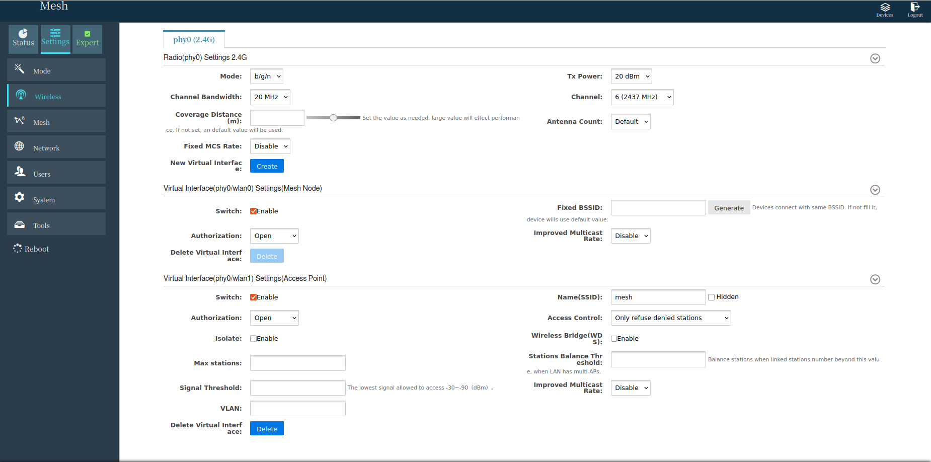
Under Settings-> Wireless (Expert Mode Enabled(checkbox)), Change Channel bandwidth, channel, Tx power as below,
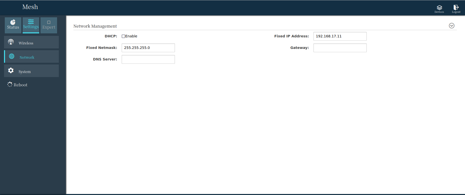
Under Settings-> Network, Change the Fixed IP Address of the ViuMesh Radio as per the Drone_ID (Refer IP Allocation Table)
Under Settings-> System, Change the Region as below,

Apply the changes and reload the mesh radio configuration webpage on the allocated ip address.
Integration ViuMesh with FC#
Now, the flight controller has to be assigned with ip address to integrate it with the Viumesh, which will help to connect and communicate with QGC using ViuMesh
note
The given parameter file should be able skip the next step
PX4 configures the serial port to connect to a GCS via MAVLink, using the parameters shown below:
| Parameter | Value | Description |
|---|---|---|
| MAV_2_CONFIG | 1000 | Configure Ethernet port |
| MAV_2_BROADCAST | 1 | Broadcast HEARTBEAT messages |
| MAV_2_MODE | 0 | Send the "normal" set of MAVLink messages (i.e. the GCS set) |
| MAV_2_RADIO_CTL | 0 | Disable software throttling of MAVLink traffic |
| MAV_2_RATE | 100000 | Maximum sending rate |
| MAV_2_REMOTE_PRT | 14550 | MAVLink Remote Port of 14550 (GCS) |
| MAV_2_UDP_PRT | 14550 | MAVLink Network Port of 14550 (GCS) |
Setting up ethernet address for the flight controller,
Open QGC->Analyze Tools->Mavlink Console
Check the current network settings netman show # to show the current ethernet settings
Create network settings file using the following commands. The following commands will create a file on the microsd card, and px4 will replace the previously shown network settings with the below on next boot or netman update command
echo DEVICE=eth0 > /fs/microsd/net.cfg echo BOOTPROTO=static >> /fs/microsd/net.cfg echo IPADDR=192.168.17.xx >> /fs/microsd/net.cfg #ip address that need to be assigned to the FC echo NETMASK=255.255.255.0 >>/fs/microsd/net.cfg echo ROUTER=192.168.17.yy >>/fs/microsd/net.cfg #ip address of the corresponding ViuMesh echo DNS= 192.168.17.yy >>/fs/microsd/net.cfg #ip address of the corresponding ViuMeshNOTE: You can refer to the IP Allocation Table for reference.
After the above step, you can use cat /fs/microsd/net.cfg on the mavlink console to check the network settings you have created using previous step
Reboot the flight controller or use netman update command on the mavlink console to update the network settings
Power up FC and ViuMesh, use ifconfig on mavlink console to check whether the network is UP & established
IP Allocation Table#
| Drone | Drone_ID | OBC IP | ViuMesh IP | FC IP |
|---|---|---|---|---|
| Aira-01 | 0101-SDP-001 | 192.168.17.10 | 192.168.17.11 | 192.168.17.12 |
| Aira-02 | 0101-SDP-002 | 192.168.17.20 | 192.168.17.21 | 192.168.17.22 |
| Aira-03 | 0101-SDP-003 | 192.168.17.30 | 192.168.17.31 | 192.168.17.32 |
| Aira-04 | 0101-SDP-004 | 192.168.17.40 | 192.168.17.41 | 192.168.17.42 |
| Aira-05 | 0101-SDP-005 | 192.168.17.50 | 192.168.17.51 | 192.168.17.52 |
| Ground Station | 192.168.17.100 (Laptop) | 192.168.17.01 |