camera-flash-wiring
Camera and Strobe wiring#
The following below is based on the set used on cam 4. Feel free to modify to simplify/improve the design.
Wiring diagram
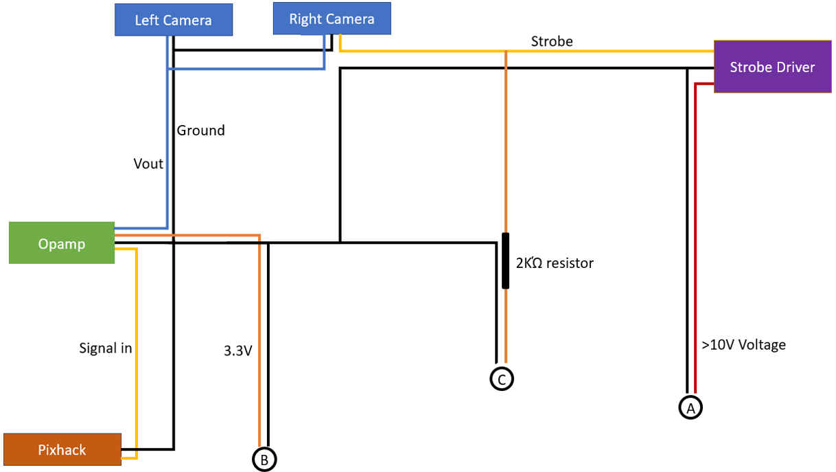
Camera trigger Opamp
Camera trigger signal from pixhawk/pixhack has a voltage of 2.3V, while the camera modules require 3.3-5V in order to be counted as an active high signal. An opamp is hence used to amplify the signal.
Model: SparkFun OpAmp Breakout - LMV358 Purpose: Amplify signal between pixhawk AUX pins and Camera
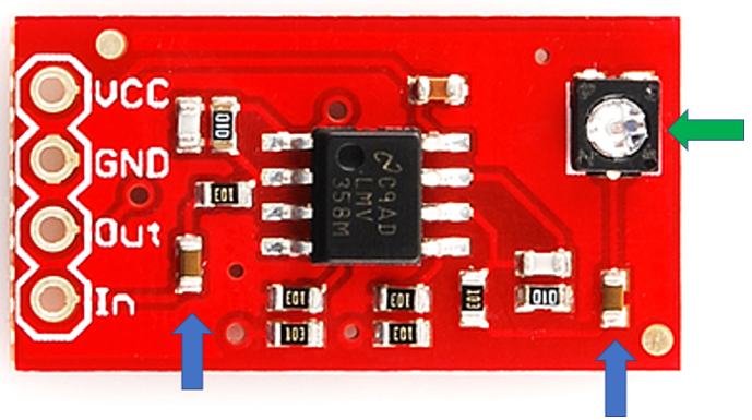
Procedures:
1) Remove the two resistors as above and short using solder. (Blue arrows)
2) Connect corresponding wires
- Vcc: External 3.3/5V voltage from Pixhawk(Serial, GPS port, etc), or Battery
- Gnd: Ground wire.
- Out: Out trigger wire, to both camera modules.
- In: Signal in from Pixhawk/Pixhack.
3) Connect OUT signal to Oscilloscope, adjust knob (green arrow) till amplified signal can be seen(3.3V - 5V). Fixed the knob with hot glue.
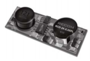
LED Flash driver
Model: RCD-24-PL
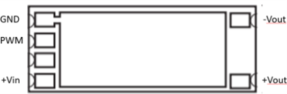
Pinout
- Gnd: Ground
- PWM: Connected to Strobe out port from one or both camera modules
- +Vin: >10V voltage from battery
- +Vout/-Vout: To flash unit
Strobe setting(Inside tcam capture)
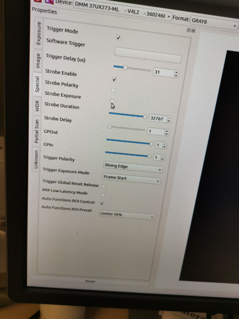
Important settings:
- Strobe enable: [✓]
- Strobe exposure: [x]
- Strobe polarity: [x]
- Strobe duration:Substainable (>10K)
- Strobe delay : 0
- Trigger polarity: Rising edge
- Trigger exposure mode: Frame start